At the moment, there are two main ways to test how resistant high-performance concrete is to chloride ion penetration: the natural penetration method and the accelerated penetration method.
Rapid Chloride Penetration Test
- Natural penetration
The natural infiltration method is to soak the concrete for a long time in water with chlorine salt, then slice or drill core samples, use chemical analysis to find the relationship between the concentration of chloride ions and the depth of penetration, and then use Fick’s second law to figure out the concentration of chlorine ions.
- Ion permeability coefficient
This is the most common way to figure out the permeability coefficient of ions in concrete. It is close to what happens in real life, but it takes a lot of time and work.
- Accelerated Penetration
Using an electric field, the accelerated infiltration method speeds up the movement of chloride ions in the concrete. This cuts down on the time it takes for the chloride ions to reach a steady state transmission process.
- The electric flux method
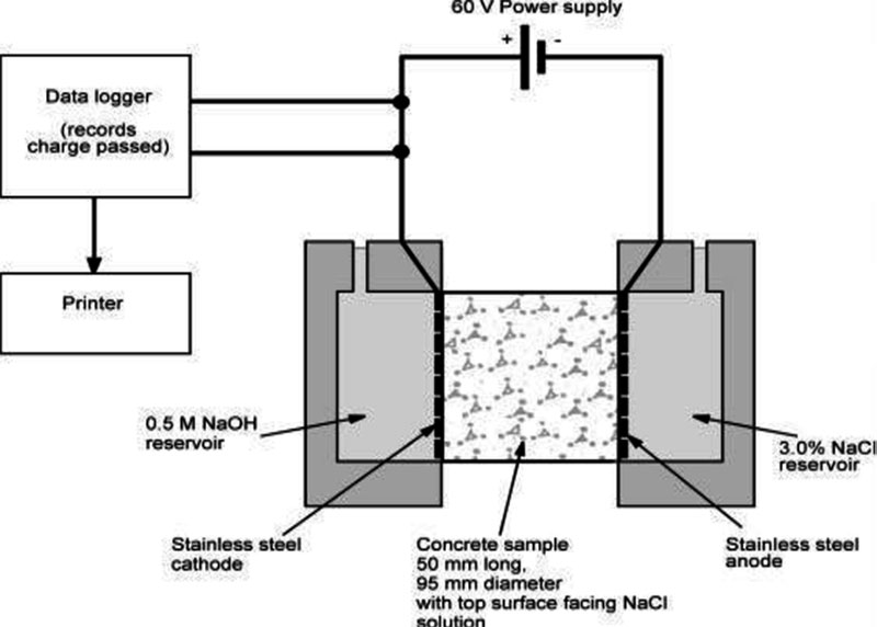
Whiting came up with the electrical (direct current) accelerated chloride diffusion test in 1981. It was called the Rapid Chloride Penetration Test at the time (RCPT). The device is based on the idea that ions in a solution can move quickly when an electric field speeds them up.
This device used 60V of electricity. Due to the short time this test method takes and the fact that it can be used again and again in the lab, it was chosen as a standard test method by the US Bureau of Highway Transportation (AASHTO T277) in 1983. It was then chosen by the American Society for Testing and Materials (ASTM).
- Standard test method
The specific method of the AASHTO T277 (ASTM C1202) test: An electric field of 60V was put on a piece of concrete that was 50 mm thick and 100 mm in diameter. The solutions used in the two ends of the water tank were 3.0% NaCl and 0.3M NaOH, respectively, for 6 hours.
During this time, the level of concrete electricity is used to figure out how well anti-chloride ions can get into the concrete. Even though this method of testing chloride penetration was chosen as the standard test method, there are still a few points of contention:
- The electricity going through the test piece is related to all ions in the pore fluid, not just chloride ions;
- The test work is done before the ions reach a stable migration, which means that the diffusion of the ions has not reached a steady state;
- The added high voltage causes the temperature of the solution to rise, which changes the test results;
- Serious electrode corrosion; and
- The measured results cannot accurately and quantitatively describe the ability of the electrode to conduct electricity.
The method of permeability coefficient
1) The relationship between concentration and flux, penetration depth, and penetration coefficient was first set up theoretically using the Nernst-Planck equation. This was then tested in the lab. The European Union has mostly agreed with Tang Luping’s test method, and it is recommended as an EU standard. But this method doesn’t solve the problems with the chloride ion penetration test in a fundamental way.
2) Resistance technology is another way that has been created in recent years to measure how well chloride ions can get into concrete. The substance’s resistance to electricity is called its resistivity, and the opposite of resistivity is conductivity. According to St. Reicher and Alexander, the conductivity of saturated porous materials is primarily determined by the conductivity of the pore liquid:
F =σ/σ0
Medium σ——the conductivity of the porous material;
σ0 ——the conductivity of the pore liquid.
The conductivity and diffusion coefficient of porous materials are influenced by the same factors, namely the pore size and its connectivity. Therefore, it can also be expressed as:
F = D/ D0
where D is the diffusion coefficient of the porous material;
D0 – the diffusion coefficient of chloride ions in the pore liquid (ie the diffusion coefficient of free chloride ions).
There are two ways to test the value of resistance. You can use direct current or alternating current. Most of the time, 10V or less is used to test the resistance of concrete, and the test time is very short so that the concrete doesn’t get too hot. The hardest part of this test method is to figure out how the pore fluid conducts electricity. There are two ways to get the pore solution out of the concrete: the pore solution extraction method and pre-saturating the concrete to be tested with a known-conductivity solution. The pore solution extraction method is the most common.
Downsides to resistive technology:
1) The drying process of pre-saturation technology causes tiny cracks, which damage the original pore structure of concrete and make it more permeable. At the same time, it is hard to make sure that the solution is spread out evenly on the concrete. Even with vacuum saturation technology, it is hard to make sure that high-quality concrete and thicker concrete are completely saturated.
2) It is not true that the solution is the same before and after it goes into the concrete. This is because the ions in the concrete pore liquid are different (mostly alkaline hydroxides), and when the concrete dries, these ions are oversaturated and form crystals. When these crystals are solid, they will dissolve in the solution, which will change how well the solution conducts.
3) It is hard for ions to get to a steady state when they move.
4) Not suitable for electrically conductive materials.
The problem with the above permeability models is that they assume the permeability coefficient is always the same and don’t take into account how the movement of water affects the movement of compounds.
While the measurement period is long, the permeability coefficient changes with time, and the matching value cannot be obtained when measuring concentration. This permeability coefficient cannot effectively measure high-performance concrete’s durability. By figuring out relative permeability coefficients, these models can be used to compare how permeable different concretes and concretes in different situations are.
Currently, the primary problems are conducting long-term chloride ion penetration tests of concrete in natural environments and accelerating chloride ion penetration tests in laboratories according to a certain area and practical application situation, combined with the coupling effect of various factors.
The effect of different environmental conditions and strengthening factors is studied, and test data is analyzed scientifically to build an analytical model for natural and accelerated chloride ion penetration, which can be used to accurately predict how long a concrete structure will last.
Permeability determines concrete durability, and chloride ion penetration resistance is an effective measure and index. Long-term, systematic scientific research is needed to figure out how and how much chloride ions can get through concrete when many different factors work together.
Anti-chloride ion penetration test
Measure the electric flux passing through the sample, and use this as an index to determine the resistance of the sample to chloride ion penetration.
Test equipment: chloride ion flux tester, vacuum container, vacuum pump, distilled water, 3% NaCl solution, NaOH solution, silica gel or resin sealing material, hair dryer, φ100mm100mm mold test.
Test sample: a cylindrical sample with a mass fraction of fly ash of 45%, an additive amount of 10%, constant temperature, constant humidity, airtight bag curing for 60 days, diameter (100±1) mm, and height (50±2) mm.
Number of samples: 3.
1. Sample pretreatment
1. When making samples in the laboratory, use a 100mm100mm mold. The age of 53 days are sampled. The test sample is a (50±2) mm high cylinder cut from the sample.
2. When the sample reaches 60d, take it out of the curing box, leave it out in the air until the surface is dry, paint the cylindrical side with silica gel or resin sealing material, and fill the coating holes.
3. Place the sample in the vacuum container, turn on the vacuum pump, and drop the absolute pressure to (1~5) kPa in 5 minutes, maintaining the vacuum for 3 hours. Add distilled water to submerge the sample. Reduce pressure after 1 hour and soak for 182 hours.
Electric flux test operation steps
1. After saturating the vacuum with water, remove the sample, brush off excess water, and keep the relative humidity above 95%. Screws fasten the two test grooves and the sample with the vulcanized rubber pad on the end face. Check the sample’s seal with distilled water after installation.
2. After confirming the sample and the test tank’s tightness, inject the NaCl and NaOH solutions. The negative pole of the power supply is connected to the net, and the positive pole is connected to the copper mesh that has been injected with NaOH.
3. After connecting the power cord correctly, turn on the power supply while the test tank is full of solution, and apply (60) V DC constant voltage to the two copper meshes above. Record the initial current reading, IO. At first, every 5 minutes is recorded. When the current changes a little, record it every 10 minutes; when it changes very little, record it every 30 minutes for 6 hours. (You can also use test equipment that collects data on its own, and the current measurement value is correct.)
4. After the test, drain the test solution, rinse the test tank with cold boiling water and detergent for more than 60 seconds, and dry it with a hair dryer.
Data processing
1. After the test, draw the relationship between current and time with the time as the abscissa and the current value as the ordinate. Connect the data of each point with a smooth curve, and integrate the area of the curve to obtain the electric flux C passing through the test for 6h.
2. The total electric flux of each sample can be calculated by the following simplified formula:
In the formula: Q—the total electric flux (C) passing through the sample;
IO—Initial current (A), accurate to 0.001A;
It—current (A) at time t (min), accurate to 0.001A.
3. Convert the total electric flux across the sample to its 95mm diameter. Multiply the computed total electric flux by the ratio of a 95mm diameter sample to the actual sample cross-sectional area, where:
Qx—the electric flux (C) passing through the sample with a diameter of x (mm);
Qs—electric flux (C) passing through a sample with a diameter of 95 (mm);
x—the actual diameter of the sample (mm).
- 4. Take the arithmetic mean of 3 samples’ electric flux as the group’s measured value. When the difference between one electric flux value and the middle exceeds 15% of the middle, the arithmetic mean of the remaining two samples is used as the experimental result. When the difference between two measured values and the middle exceeds 15% of the middle, the middle value is used for this group’s electric flux test result.